Modern LED Video Screens: Characteristics, Technologies, Reasons to Choose – Part 2
The first part of the article was devoted to some essential characteristics of modern LED screens that affect image quality, including brightness control with PWM, method of creating image with time multiplexing and refresh rate. The second part focuses on dynamic color range, color rendering, contrast, IC drivers and control system, electromagnetic compatibility and industrial interference from LED screens.
Dynamic brightness range, color rendering and contrast of a LED screen
Brightness and color rendering on a LED screen
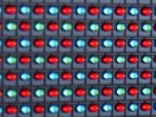 Fragment of a LED module for outdoor screen with 2R1G1B pixel structure
An essential parameter of LED screens is an ability to display a certain number of colors. All visible colors result from color mixing of basic colors that make up a pixel, typically, Red (R), Green (G) and Blue (B). Apparently, the more colors a screen may render, the higher the image quality, provided that the colors are natural and color transitions are smooth.
Initially, the image is formed on a computer and image quality is evaluated on a PC monitor. The image on a LED screen must be as close to the initial image as possible. A current de-facto standard is a 24-bit color coding (TrueColor) where the brightness value of each channel is presented as a 8-bit number. Thus, ideally, a high quality LED screen should render at least 224 colors (or more than 16 million).
We already analysed how the image is generated on an LED screen with the help of PWM technique. The more logical levels are supported by PWM on a given screen, the higher is the image quality.
PWM method establishes a linear dependence between current (average value) and logical level of brightness. Thus, PWM with N levels ensures that the real brightness of LEDs for all these levels will change linearly. In other words, the brightness of an LED with PWM at level 1 will be exactly twice lower that at level 2 and 256 times lower than at level 256.
N logical levels in PWM corresponds to N brightness levels of LEDs on screen and the actual brightness directly depends on the input level. However human eye perceives brightness in a non-linear fashion. The empiric psychophysical Weber-Fechner Law postulates the logarithmic function as a method for human perception of light intensity.
At lower intensity human eye will notice even the insignificant changes in brightness; at higher intensity similar insignificant changes in brightness will go unnoticed. A much bigger change will be needed to register with the eye. Let us imagine all possible brightness levels N (with N being no less than 100) as a horizontal line with 100 segments. The eye will easily perceive adjacent segments of brightness at the beginning of the line, then in the center the difference between adjacent segments will not be evident, and at the end of the line – not noticeable at all. In reality this means that out of the total number of N levels we can select a much smaller number of levels M that will be perceived linearly.
It’s interesting to learn that the image generation on LCD monitors takes this quirk of human perception into account. In CRT-monitors this is a direct consequence of image formation method; in LCD-monitors a hardware gamma correction is utilized. All this results in a relatively linear function that describes the subjective perception and the coded logical level of brightness. Thus, the initial image file has 256 brightness levels (for TrueColor) in each channel that are perceived in a linear fashion.
If PWM with 256 logical levels is used to display an initial TrueColor image, we will notice visible distortions. On dark sections of the image we will see sharp borders between brightness segments, on bright sections all brightness levels will merge. Distortions will affect the colors, especially where a smooth color gradient is essential, e.g. on a picture of a human face. This happens because the initial image uses 256 non-linear levels which are converted on a screen in a linear levels – unsuitable for human eye perception.
For TrueColor image to be rendered on an LED screen with minimum distortions, the logical brightness levels have to be corrected. This can be achieved by increasing the number of logical levels on a PWM-generated image. Then, out of the much larger number of levels it will be easier to select 256 levels that can be coded for a linear perception. This selection of 256 levels out of a much larger number is called “a gamma correction” or “a choice of palette”. The more brightness levels can be generated via PWM, the easier it will be to make a correction so that colors and brightness are perceived in a “proper” linear format.
At present the best LED screens offer PWM with 216 logical brightness levels. This is more than enough to select the necessary 256 levels to display accurate TrueColor image. It should be noted that an LED screen can display 256*256*256 colors, and not 216*216*216; it means that color is still coded by a 24-number, not a 48-bit. The artificially expanded color palette is only necessary to select the minimum necessary number of colors to ensure natural color and brightness perception.
Each channel may be coded in 8, 10, 12, 14–bit or maximum 16-bit brightness. On lower channel codes the correction will naturally be less effective. On the other hand, an LED screen with smaller number of logical brightness levels will be cheaper while accurate TrueColor rendition on screen is not always necessary. For example, LED signage with running letters or informational digital signs do not need huge number of colors.
Wider color range is preferable for several other reasons:
- First, it allows to adjust LED screen brightness depending on the time of the day, season of the year, peculiarities of screen site. Human eye adapts flexibly to general lighting conditions; therefore, screen brightness on a sunny day and during the night should be drastically different. Moreover, if a LED screen is installed on the background of the sky, it’s adjustment parameters must differ from a similar screen standing in front of a building or hanging on the wall.
- Secondly, it allows for flexible adjustment of white balance. Palettes can be selected independently on each color channel; thus, we can add blue or reduce red in a target image. This is essential for both the initial screen settings and later adjustments that are necessary due to aging of LEDs (LEDs losing brightness with age) or LED lens losing opacity.
- Thirdly, it allows some color correction in individual LED screen modules. This may be necessary when some modules fail and are replaced by spares: in this case LED parameters in new and adjacent modules will be different and need tuning.
This function is essential for the control system, too. It is not enough to make 16-bit PWM; manufacturers must have the option of flexible brightness adjustments in the hardware and software of the control system. Otherwise, this important application will have no practical use.
Contrast on a LED screen
Contrast is an essential parameter of color rendering on a LED screen. Contrast is the difference in visual properties that makes an object (or its representation in an image) distinguishable from other objects and the background. In case of a LED screen if the black color is not really “black”, then the human eye will not distinguish the details on dark image areas – they will merge will less dark areas. Black color on a LED screen has nothing to do with performance of an LED – black background is created by materials used manufacture a LED screen.
Problems may result from reflection of sunlight from LED screen surface: in this case when all LEDs are switched off the screen surface may appear whitish in color. This effect is caused by white LED epoxy lens, shiny black surface of protective plastic between LEDs, incorrect position of protective louvers or even light-color LED padding. In general, the better is the matte dark surface of an LED screen the higher is the contrast and image quality.
Number of colors and cost of a LED screen
Number of colors on a LED screen may only be increased by:
- using “intellectual” IC drivers;
- increasing PWM frequency;
- reducing refresh frequency.
Brightness, color rendering and contrast of a LED screen: Conclusions
- The more brightness levels are generated by PWM, the easier it is to fine-tune LED screen to accurate color rendering.
- Color adjustment must be available on all control system components: from software to LED drivers. Theoretically calculated number of colors runs into billions and trillions. However, the system is not always capable of displaying all these hues.
- Image quality is affected by components used for manufacturing LED screen surface: it should be as dark and matte as possible.
IC Drivers on LED screens
An LED driver is a microchip supplying constant current to LEDs. IC drivers are based on integrated command circuits. In the simplest form it may be an “on-off” command. In more complex “intellectual” drivers commands include the possibility to control LED brightness via PWM.
With simple drivers, PWM function has to be handed over to controllers that will send a command to drivers about switching LEDs “on” and “off”. Advantages are evident: simple drivers are cheap. Disadvantages are many: controllers become more complex, it becomes difficult to generate the necessary number of brightness levels and refresh frequency. To achieve high image quality controllers must operate in high frequency mode and transfer data to drivers. But these frequencies have technological limitations.
“Intellectual” drivers take over some of the above functions and simplify operation of controllers. But the LED screen cost goes up. To justify this cost increase, the control system must be sufficiently sophisticated to support all new functions of IC drivers and thus relay high quality image on screen.
To sum up, IC drivers have the following essential features:
- number of channels;
- output current (range, stability);
- clock frequency;
- PWM free-running capability;
- control current output for each PWM channel;
- internal oscillator;
- number of channels (interface width);
- additional feedback capability (overheating, LED open/short);
- digital dot-correction;
- digital brightness correction;
- IC driver package: SOP, SSOP, QFN.
LED drivers are developing following several trends:
- Upgrading of “simple” drivers. Additional functions are introduced: e.g. diagnostics and brightness control or increased frequency of data transfer.
- Upgrading of “intellectual” drivers. New functions appear and quantitative parameters improve (frequency, number of PWM levels). Advanced LED drivers support 16-bit PWM at frequencies nearing 20 МHz and wide range of service and feedback functions.
- Numerous specialized drivers with certain fixed functions appear: for instance, DM163 with 24 channels, 8-bit PWM and 6-bit brightness correction. This also concerns drivers with in-built clock support, e.g. MBI5050.
It is a tradition already to make drivers with 8 or 16 channels. However this is not always suitable for LED screens because modern pixel usually consists of 3 LEDs which complicates the topology of the PCB. Technologically, it would be more convenient to place one driver in the center of a 4-pixel cluster.
Unfortunately, most companies involved in design and manufacture of IC drivers tend to make “all-in-one” products. Sophisticated modern drivers, they have the widest possible range of functions. Customers rarely use all these functions but have to pay for them. For example, an excellent DM634 boasts 16-bit PWM and 7-bit general brightness correction. The latter function is superfluous at best, because with 16-bit PWM and modern LED screen control system it is possible to ensure general brightness correction via other methods.
The problem of external interface stands separately. Different drivers enable data transfer and PWM control in different ways – not always convenient from the point of view of the control system. With no unified approach to design of drivers and control system, the problem gradually deepens: each type of drivers requires different interface block. Thus, practically, each LED screen has a unique control system.
Customers buying LED screens know little if anything about LED drivers. They learn about the acceptable screen parameters in terms of refresh and brightness levels – but these parameters are frequently misleading. Driver consumes a lot of energy and heats a lot. With poor module design, IC drivers will overheat and lead to LED and module failures.
For a developer of LED screen control system to choose a driver is a difficult choice between necessary screen parameters and price.
Modern control systems for LED screens
Generally speaking a control system includes a source of video information on the high level (PC, specialized player), a software, a set of controllers that ensure data feed and conversion, and LED drivers connected with controllers into a single network and transferring digital signal into current forwarded to LEDs.
Control system is a link between numerous subsystems of a LED screen and the actual image that we see on a screen. Moreover, a control system must offer an option of linking several LED screens into a network similar to an office network of PCs.
Here are some functions essential for a modern control system
- Control system must channel video signal utilizing most functions of LED drivers;
- Control system must have a modular structure to utilize different hardware functions;
- Control system must be coordinated with scheduling software to offer the best options in scheduling clips on a LED screen;
- Control system must have flexible adjustment of colors and brightness;
- Control system must allow flexible adjustment of LED screen geometry since similar modules can be arranged in LED screens of different shapes and sizes.
Network function of a LED screen control system
An important option is to add individual screens to a larger LED screen network. To do this, the control system must support network interface for scheduling advertising clips and content and individual settings of screens.
Ideally, control system must be modular. In this case it’s possible to subdivide network functions and control of image generation. New option appears to build heterogeneous networks consisting of LED screens of different architecture, and even including LCD displays. The general control over the network will be exercised from a unified control center.
Currently, LED screen networks are controlled via the Internet. The network functions of control systems must include this option.
Monitoring of a LED screen
Control system must include functions of monitoring and feedback that includes:
- Scheduler log that records what video clips were displayed on a LED screen;
- Hardware log that records all defects and failures of the equipment. The more sophisticated the control system, the more detailed is this technical feedback;
- Access log that records each entry into the system and each change in screen settings.
Information security of the LED screen control system
An LED screen is controlled by a PC. Any number of people may have access to a controlling PC. Therefore, the control system must have in-built information security functions.
This information security subsystem have the following safeguards:
- Primarily, ways to prevent an unauthorized display of information on a LED screen;
- Automatically generated logs must be protected from tempering;
- Security subsystem must have options of running LED screen as part of the larger network and as an individual screen, too;
- Integration with control system so that it could not be removed or deleted from the screen.
Electromagnetic compatibility (EMC) and electromagnetic interference (EMI) of LED screens
Large LED screen has many electronic components and is controlled via digitals system. This makes an LED screen similar to any electronic device when part of the consumed electrical power is emitted as electromagnetic radiation capable to induce electromagnetic interference (EMI).
This radiation results from high frequency switching of a very large number of components. Data and signals moving between PCBs generate radiation. An LED screen consists of many similar components – LED modules. The geometry of PCB layout multiplied dozens of times creates a gigantic antenna.
Electromagnetic interference (EMI) may interrupt, obstruct, or otherwise degrade the quality of radio and TV services or radio phones.
Minimizing the radio interference is the important task for developers of LED screens who understand in details all the intricacies of electronic design. This task may only be achieved by complex measures in developing electronic layouts, designing safe LED modules, controllers and wiring.