LEDs are still popular and improving after all these years: Part 2
What are LEDs?
A light emitting diode (LED) is a p-n junction semiconductor diode that emits photons when forward biased. The light emitting effect is called injection electroluminescence, and it occurs when minority carriers recombine with carriers of the opposite type in a diode's band gap. The wavelength of the emitted light varies primarily due to the choice of semiconductor materials used, because the band gap energy varies with the semiconductor. Not all injected minority carriers recombine in a radiative manner in even a perfect crystal; non-radiative recombination occurring at defects and dislocations in the semiconductor can give rise to wide variations in useful emissions in seemingly identical diodes. This means in practice that manufactured batches of LEDs are sorted and graded for intensity matching.
 |
 |
| Fig. 3 Typical GaP LED die | Fig. 4 Typical LED indicator and cutaway showing construction |
LEDs are processed in wafer form similar to silicon integrated circuits, and broken out into dice. Chip size for visible signal LEDs generally fall in the range 0.18 mm square to 0.36 mm square (Fig. 3). InfraRed (IR) LEDs can be larger to handle peak powers, and LEDs for lighting are larger again.
The simplest packaged LED product is the lamp, or indicator. The basic structure of an LED indicator consists of the die, a lead frame where the die is actually placed, and the encapsulation epoxy which surrounds and protects the die, and also disperses the light (Fig. 4). The die is bonded with conductive epoxy into a recess in one half of the lead frame, called the anvil due to its shape. The recess in the anvil is shaped to throw the light radiation forward. The die's top contact is wire bonded to the other lead frame terminal, the post.
The mechanical construction of the LED lamp determines the dispersion or radiation pattern of the light. A narrow radiation pattern (Fig. 5) will appear very bright when viewed on-axis, but the viewing angle will not be very wide. The same LED die could be mounted to give a wider viewing angle, but the on-axis intensity will be reduced. This tradeoff is inherent in all LED indicators, and can be easily overlooked. High brightness LEDs with a 15° to 30° viewing angle are a good choice for an information panel directly in front of an operator, but a wide direction indicator or automotive dashboard might require as wide an angle as 120°.
 |
 |
| Fig. 5 Narrow LED indicator radiation pattern | Fig. 6 7-segment, 14-segment, 16-segment, and 5x7 matrix digit types |
The familiar 7-segment numeric display digit actually suffers from a misnomer, as there's nearly always an 8th segment for the decimal point (DP). The less familiar “starburst” alphanumeric displays are similarly referred to as 14-segment and 16-segment digits, ignoring the DP again. Starburst displays provide an economical way of showing the full 26 characters of the Roman alphabet, in upper case, as well as the numerals 0-9. The difference between the 14-segment and the 16-segment digit types is that the top and bottom bar is split on the 16-segment digit, improving the appearance of some characters (Fig. 6).
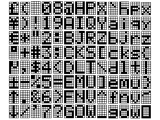
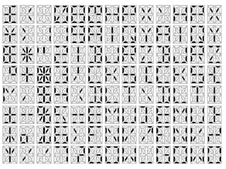
The 5x7 matrix is even more versatile, capable of displaying the Roman alphabet in both upper and lower case as well as a wide of symbols. The difference in the display quality is shown in Fig. 7, which compares the characters displayed using the 5x7 matrix font map of the Maxim MAX6952/3 display driver with the characters displayed using the identical font map of the Maxim MAX6954/5 starburst display driver. The 5x7 matrix is inadequate for CJK (Chinese-Japanese-Korean) characters, and a font granularity of 12x12 is often cited as a minimum resolution.
 |
 |
| Fig. 7 Comparing 5x7 matrix and starburst characters | |
Most LED numeric and alphanumeric display digits are actually hybrids, mounting multiple LED chips in a package. Some very small display digits (for example the “bubble-top” calculator displays popular in the 1970s) are monolithic. Either way, the shape of each segment is defined by a reflector and light pipe mounted around the LED die, not by the die itself. Small displays use one die per display segment, while large displays may use 2 or more dice per segment to spread the light effectively and show reasonably uniform intensity across the segment.
In the manufacturing process, the chips are mounted on either a lead frame or a PCB, and wire bonded to an interconnection pattern. The dice are mounted using conductive paste, because the die substrate forms one of the two diode connections (Fig. 8). The interconnection pattern usually connects either the anode or the cathode LED chip connections together to reduce the number of pins required for the digit. As a result, displays are referred to as CA (common anode) or CC (common cathode) types, and integrated circuit display drivers will specify one type or the other (Fig. 9).
 |
 |
| Fig. 8 Mounting an LED die to form a digit segment | Fig. 9 Common anode and common cathode LED digit types |
The lead frame method of construction is similar to that used for integrated circuit manufacturing. The frame is normally etched silver plated steel, providing good heat conduction and light reflection. The reflector channel forming the light pipe for each segment is epoxy filled during construction, and the epoxy provides the mechanical strength and the environmental protection to the display.
A cheaper construction method uses a PCB type substrate instead of a lead frame. Displays built this way are often referred to as “stick” types, because the method is commonly used to build multi-digit displays, for example 4-digit clock LEDs. Stick construction allows the display to be built without epoxy fill, which saves cost but leaves the display susceptible to degradation from contaminants.
LED Electrical and Optical Characteristics
The electrical behavior of LEDs is similar to other semiconductor diodes. The forward voltage is higher, and is different for the different materials used for different colors (Fig. 10). The forward voltage rises with current, and falls with temperature by about 2mV/°C. And, like all semiconductors, the LED must be derated at higher operating temperatures.
The optical behavior of the LED varies significantly with temperature. First, the amount of light emitted by the LED lamp falls as junction temperature rises. This is because of an increase in the recombination of holes and electrons that make no contribution to light emission. Also, the emitted wavelength also changes with temperature, mainly due to the semiconductor energy gap changing with temperature.
 |
 |
| Fig. 10 LED forward voltage varies with color and current | Fig. 11 LED light output vs. current |
Driving LEDs: Static drive and Multiplex Drive
The easiest way to drive multiple LEDs, such as display digit segments, is to drive each LED separately, each with a resistor or current source setting the forward current. This technique is called static drive because the LED current is continuous. Static drive is useful when relatively few LEDs are driven, with the sensible limit being about two 7-segment digits. High efficiency LEDs can be driven to high brightness with 2mA, which is available from the output ports of most microcontrollers.
When a lot of segments are to be driven, static drive demands an uneconomic number of drive outputs, 1 per LED. Multiplex, or pulse drive reduces the drive connections by strobing only a small number of segments (typically a complete digit) at a time. The strobing is done at a high enough repetition rate that the eye perceives continuous illumination. However, the LEDS must be driven at a higher current to compensate for the reduced duty cycle.
An advantage of pulse drive is that the human eye behaves as a partially integrating and partially peak reading photometer. As a result, the eye perceives rapidly pulsed light somewhere between the peak and the average brightness. This means that a low duty cycle high intensity pulse of light looks brighter than a DC signal equal to the average of the pulsed signal. Therefore one advantage of multiplexed operation is an improvement in display intensity for a given average power consumption.
The efficiency of an LED typically rises with forward current, presuming constant junction temperature. This is not always the case however, and LED data sheets should be examined (and compared) carefully when choose the optimum peak current (Fig. 11). However, multiplying can often provide 1.5 times the light output from the average drive current of the cycle, compared to the equivalent DC level.
As LED drive currents increase for multiplexing, internal temperatures within the chip also increase. There is a point where the effect of the temperature increase is such that the drop in photon conversion efficiency, due to the higher temperature, negates the effect of the increased current density through the junction. At this point increasing drive currents can result in little, no change, or even decreases in light outputs from the LED chip.
The standard connection for multiplexing LED digits uses a separate pin for each digit' common cathode connection, while the anode segment connections are commoned across all the digits (Fig. 12). The number of connections required can be calculated as being 1 for every digit used, plus 1 for every segment within a digit. A more pin-efficient scheme relies on the fact that during the multiplex operation, only one digit drive output is actually in use. By making the LED drive pins alternate duty between driving digits and segments, n drive pins can be used to drive n digits each with n-1 segments. This technique is used in the Maxim MAX6951 LED driver to drive 8 numeric digits with only 9 pins (Fig. 13).

Fig. 12 Standard connections for multiplexing

Fig. 13 Reduced pin-count multiplexing - MAX6951 connections


